
Background
Bioswale is a vegetated swale with a parabolic or trapezoidal cross-section, with a filter media system that temporarily stores and then filters or infiltrates the desired design storm volume. As the water passes through the media, soil microbes break down pollutants, and plants take up some of the water and use available nutrients for growth. The rest of the water moves down through the soil to recharge the groundwater table or flows through an underdrain pipe system. Vegetation/plants, through their pollutant uptake and evapo-transpiration of stormwater runoff, play a key role in the overall effectiveness and function of the Bioswales.
Purpose
Currently, the Department of Inspections and Permits (I&P) does not have published guidance regarding the design, construction, and maintenance of Bioswales. The purpose of this notice is to provide guidance regarding bioswales as they relate to development projects. The County recognizes that BMPs including Bioswales are designed, reviewed and approved based on many factors including but not limited to site conditions, Watershed conditions, Terrain, Stormwater Treatment Suitability, and Physical Feasibility – This guidance is not intended to cover each and every design scenario or site condition the design professional may encounter in the design of Bioswales or other BMPs. Maryland Department of Environment (MDE) approved this guidance on November 15, 2024. Several items from this guidance (e.g., filter media, compaction, maintenance, vegetation, soil borings, non-stormwater runoff, or other design elements) also apply to other filtration, infiltration micro practices. The designer should apply those guidelines as appropriate for other practices as well. Where underdrain is proposed, the designer may propose an Internal Water Storage (IWS). More information on IWS.
Bioswales Guidance
The following shall be considered in the application and implementation of Bioswales:
1. Applications
Bioswales can be used for new development, retrofitting and redevelopment applications. The linear structure allows use in place of curb and gutter along highways, residential roadways, and along property boundaries. Bio-swales may include an underdrain, as required by the site soil conditions. Extreme temperatures and frozen ground need to be considered when calculating design volumes. Bioswales may not be designed to provide stormwater detention. Bioswales are generally impractical in areas with very flat grades (0.5% or less) or steep topography.
Bioswales shall not be used to treat hotspots that generate higher concentrations of hydrocarbons, trace metals, or toxicants than are found in typical stormwater runoff and may contaminate groundwater.
The drainage area contributing to all types of swales (grassed, Bioswale, wet, dry swales, etc.) should be less than one acre. Bioswales should not be designed to meet Qp (overbank Flood Protection Volume) or Qf (Extreme Flood Volume) requirements. Bioswales should safely convey runoff for these larger storm events.
2. Conveyance
Stormwater discharged into and through swales needs to be non-erosive. Sheet flow should be promoted wherever possible using precise grading, level earthen weirs, or pea gravel diaphragms. If concentrated flow is delivered from curb cuts or storm drain pipes, energy dissipation (e.g., plunge pools or rip-rap) is needed. Swales shall be designed to safely convey the 10-year, 24-hour storm at a non-erosive velocity (~2.5 fps) with at least six inches of freeboard. The maximum flow velocity for the ESDv shall be less than or equal to 1.0 fps.
All stormwater conveyance systems including bioswales and grassed swales shall be designed so that no building or habitable structure, either proposed or existing, is flooded or has water impounded against it during the 100-year storm event. Design plans shall show overland relief paths for these storm events and ensure that no structures and properties are negatively impacted or have water impounded against during these storm events.
3. ESDv and WQv Credit
The designer shall carefully evaluate the Bioswale as a conveyance practice, while ensuring the required ponding depth to be achieved and maintained, pollutant removal through vegetative filtering, sedimentation, biological uptake, and infiltration into the underlying soil media or flow through underdrains. Check dams are required for all Bioswales (refer to item #11- Check dams). BioSwales may not be “enhanced” by placing additional stone storage below the stone underdrain layer.
The average ponding depth (over the surface) for ESDv and WQv treatment should be 6 inches. Bio swales should be designed so that the desired design storm volume is completely drained within 24-48 hours.
4. Soil Borings - Siting, Suitability and Feasibility
Soil borings at the proposed facility footprint should be provided per section 5.12 of the County Practices and Procedures Manual. The number and frequency of the borings is to be determined based on the site soil characteristics and recommendations from the Geotech engineer regarding soil conditions, classification, and the homogeneous/non-homogeneous nature of the soil profiles. If groundwater is encountered, the elevation of the groundwater shall be shown in the geotechnical report and with the boring data, and also shown on the plans.
5. Clearance to Water Table
Designers shall ensure that the bottom of bioswales (with and without underdrains) is at least 2 feet above the seasonally high groundwater table, to ensure that groundwater does not intersect the filter bed, since this could lead to groundwater contamination or practice failure. If the 2 ft. clearance requirement cannot be met, a more suitable stormwater practice(s) for the site conditions must be proposed.
6. Setbacks
Setbacks shall meet requirements from Section 7.17.7 (and as updated) of the County Practices and Procedures Manual.
7. Non-stormwater Runoff - Avoidance of Sump discharges
In no event, may the sump pump discharges be piped directly to any Bioswale or SWM micro-practice (public or private). Sump discharges are generally not accounted for as a part of design of these facilities, will keep SWM practices saturated, thus compromising the design performance, capacity of the facility and affecting overall SWM design. As applicable, details of the sump pump discharges (location, outfall points, etc.) shall be provided at the building permit stage.
8. Filtering Media or Planting Soil
See Appendix B.4 of Maryland Stormwater Design Manual, Volumes I and II for material specifications for the sand, gravel, and planting soil media. Filter cloth shall not be installed on the bottom of any filtration or infiltration practice. A 4” bridging layer (#8 stone) should be used between the planting media and the #57 stone reservoir at the bottom. The planting media should be 2-4-ft thick.
The planting media shall be flooded after placement. Any settlement that occurs shall be filled back to the design elevation. The planting soil shall be tested and shall meet the following criteria:
- Soil Component - Loamy Sand or Sandy Loam (USDA Soil Textural Classification)
- Organic Content - Minimum 10% by dry weight (ASTM D 2974). In general, this can be met with a mixture of loamy sand (60%-65%) and compost (35% to 40%) or sandy loam (30%), coarse sand (30%), and compost (40%).
- Clay Content - Media shall have a clay content of less than 5%.
- pH Range – Should be between 5.5 - 7.0. Amendments (e.g., lime, iron sulfate plus sulfur) may be mixed into the soil to increase or decrease pH.
9. Compaction
It is very important to minimize compaction of both the base of any filtration or infiltration practices and the required backfill. When possible, use excavation hoes to remove original soil. If practices are excavated using a loader, the contractor should use wide track or marsh track equipment, or light equipment with turf type tires. Use of equipment with narrow tracks or narrow tires, rubber tires with large lugs, or high-pressure tires will cause excessive compaction resulting in reduced infiltration rates and is not acceptable. Compaction will significantly contribute to design failure.
Compaction can be alleviated at the base of filtration and infiltration facility by using a primary tilling operation such as a chisel plow, ripper, or subsoiler. Where bioswales are proposed in redevelopment sites, areas that are impacted by construction equipment, traffic in new development, at the bottom of the proposed bioswale, 3-5 inches of soil must be loosened, and 4-8 inches of topsoil/compost must be placed on top and not compacted.
When backfilling any filtration or infiltration facility, place soil in 12” -18” lifts. Do not use heavy equipment within the facility footprint. Heavy equipment can be used around the perimeter of the facility/basin to supply soils and sand. Grade materials with light equipment such as a compact loader or a dozer/loader with marsh tracks.
10. Underdrains
Underdrains must be proposed in C or D HSG soils or based on the site soil characteristics, soil borings information and recommendations from the Geotech engineer. The slope of the subgrade should be as flat as possible (i.e., less than 1 percent longitudinal slope) to enable even distribution and infiltration of stormwater. Designers should use a terraced subgrade design in sloped areas, especially when the subgrade slope exceeds 3 percent or more.
Underdrains should meet the following criteria:
- Pipe- Should be 4” to 6” diameter, slotted or perforated rigid plastic pipe (ASTMF 758, Type PS 28, or AASHTO-M-278) in a gravel layer. The preferred material is slotted, 4” rigid pipe (e.g., PVC).
- Perforations - If perforated pipe is used, perforations should be ⅜” diameter located 6” on center with a minimum of four holes per row. Pipe shall be wrapped with a ¼” (No. 4 or 4x4) galvanized hardware.
- The gravel layer (No. 57 stone preferred) shall be at least 4” thick above and below the underdrain. The gravel shall be cleaned and washed stone.
- The main collector pipe shall be at a minimum 0.5% slope.
- A rigid, non-perforated observation well must be provided (one per every 1,0000 square feet) to provide a clean-out port and monitor performance of the filter.
- 4” layer of pea gravel (⅛” to ⅜” stone) shall be located between the filter media and underdrain to prevent migration of fines into the underdrain.
11. Check Dams
Check dams must be used to ensure the design ponding depth is maintained, provide design storage volume, to break up slopes, and to increase the hydraulic residence time. Design requirements for check dams are as follows:
- The maximum desired check dam height is 12 inches, for maintenance purposes. The average ponding depth throughout the channel should be 6 inches. Appropriate armoring is needed at the downstream toe of the check dam to prevent erosion.
- Check dams must be firmly anchored into the side-slopes to prevent outflanking; check dams must also be anchored into the channel bottom so as to prevent hydrostatic head from pushing out the underlying soils.
- Check dams must be designed with a center weir sized to pass the channel design storm peak flow (10-year storm).
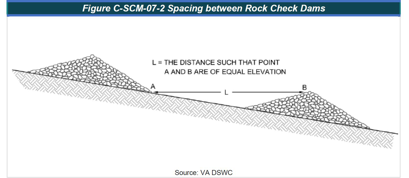
- The required spacing is determined by the following formula (see figure below- Source: VA DSWC). The spacing requirements do not change significantly with varying channel cross sections but are more sensitive to the channel slope and height of the check dam.
X = Y÷ S
where:
X = check dam spacing (ft)
Y = check dam height (ft)
S = natural channel slope (ft/ft)
12. Vegetative Cover- Planting Material
Proposed vegetation should be carefully reviewed against longitudinal slopes, drainage area, flow velocities, tolerance of species to wetness/dryness and design flows. Plants, through their pollutant uptake and evapo-transpiration of stormwater runoff, play a key role in the overall effectiveness of the Bio Swale. Plants may also be preferable to mulch since organic mulch may be a source of nitrogen or phosphorus.
Designers should consider adding perennial mix, ornamental grasses into the planting scheme; use low growing vegetation as an alternative ground cover to mulch, such as grasses, evergreens, ferns, or succulents, as growing conditions allow. Seed areas around plantings with a low ground cover seed (such as sedge, switchgrass, or juncus depending on type of facility) that will work with the plantings. The seed should be a single species to provide uniformity and make it easy to know the plant from weeds.
Designers should also review I&P blue notices IP-21-12 and IP-21-02 for additional guidance.
The best plants for bioswales are well-adapted natives including thick growing grasses or other plants with dense, deep root systems (NRCS, 2005). The thicker the vegetation and greater surface area, the more effective it will be at slowing the water and preventing erosion within the swale. Plants chosen should be able to tolerate both very wet and very dry conditions. Ideally, the swale should not need to be irrigated after the plants are established, except during times of severe drought.
Bioswales may be planted in turf grass where it is appropriate to do so, such as along roadways where visibility is a concern and where active landscape maintenance is unlikely; clear and visible signage should be posted regarding the frequency of mowing as filter media compaction is an issue with frequent mowing, ongoing maintenance. Grassed swales are planted with turfgrass that is mowed provide a more manicured look, but have been demonstrated as less effective in slowing stormwater runoff than swales with taller plants (Factsheet | HGIC 1863 |Published: May 26, 2015). A “managed turf grass” look should be avoided as much as possible. The type of grass lined in the swales should be non-clumping, deep-rooted, and rigid, as well as be managed at a height of six inches.
Native plants are encouraged in stormwater facilities (including Bioswales) because of their “greater survivorship” and tendency to require “less replacement and maintenance.” Plants must be chosen that have a high chance of thriving in the particular facility type. The top 3-5 inches of soil must be loosened, and 4-8 inches of topsoil must be placed on top and not compacted.
13. Maintenance
All Stormwater practices including bioswales shall be designed for maintenance. Maintenance for swales is generally low and includes periodic cutting of vegetation, reseeding as necessary to maintain a dense cover, watering during times of drought, and removing debris. The use of fertilizer, herbicides and pesticides should be kept to a minimum in and around the bioswale (EPA 1999).
Well-designed and maintained bioswales can be very attractive, and serve as landscaping areas within a site. Compared to other stormwater management practices, they can add aesthetic appeal to a residential or commercial site with texture, color and utility. The permeability of the filter media must be maintained or the Bioswale will fail. Vehicles and construction equipment should not be driven on the Bioswale bottom (NCDEQ, 2007) since this could compact the media or damage the underdrain. Use best professional judgment when selecting mowing and other landscaping equipment for use in the Swale. Avoid the use of riding lawn mowers and minimize foot traffic on the Bioswale bottom.
Inspection of bioswale regularly and after large storm events is required. Semi-annually and after major storm events, check bioswale and look for signs of trash and debris, sediment accumulation, clogged inlets or outlets, and erosion. As soon as possible, pick up trash and debris and use a shovel to remove accumulated sediment. If areas are eroding, repair and establish sod or use rock or special erosion-control matting to protect from further failure and slow the flow of water.
Inadequate maintenance is a frequent issue for many possible reasons, including limited resources, a lack of knowledge, or miscommunication regarding maintenance responsibility. The simplest way to minimize maintenance effort is to choose plants that are low maintenance. This includes species that require minimal trimming and fertilizer, and plants that are well matched to the climate. Plants that require little work are more likely to survive in the event of ownership transfers since their maintenance legacy is minimal.
Maintenance also includes non-routine maintenance, which is a repair performed to correct a problem and restore a facility to its proper working order.
Cattails are good indicators that water is remaining in the Bioswale longer than intended and is also an indicator of presence of sediment, silt. If this is the case, try to determine the cause of the standing water. Likely causes include a clogged underdrain system or clogged filter media, presence of sediment, silt on top of the surface. If Sediment, silt that has accumulated and is inhibiting the function of a facility it must be removed. In general, remove sediment, silt if it appears to have accumulated more than 3 inches or is impeding the function.
Fertilizers should not be applied to BMP vegetation during routine maintenance. Stormwater BMPs are designed to capture nutrients in runoff and therefore should not be a source of nitrogen or phosphorus. While a minimal amount of fertilizer may be necessary in some cases to initially establish vegetation, it should not be used during routine maintenance.
14. As-builts and Construction Inspections
For all stormwater practices, County Code requires that as-built plans and an as-built certification prepared by a design professional are submitted to the Department and during construction, I&P requires documentation of regular inspections, at a minimum, at each stage of construction. As-built plans and construction inspections documentation for bioswales shall meet the latest As-Built Checklist.
Timing and Applicability
This guidance applies to all projects where a sketch plan or preliminary plan application, as applicable, is submitted on or after the date of this memo. Where a sketch plan or preliminary plan is not required to be submitted, this guidance applies to a final plan or site development plan (SDP) submitted on or after the date of this memo. Where a final plan or SDP is not required to be submitted, this guidance applies to any new application for a grading permit, or any application for a major revision to a pending or to issued grading permit, filed on or after the date of this memo. The County strongly recommends the use of this guidance even if this memo does not specifically apply due to the timing of the submission of the final plan, SDP application or grading permit application.
References
- Chapter 3.8. Open Channel Systems – Stormwater Management Guidebook, District Department of the Environment, August 2012.
- AN INTRODUCTION TO BIOSWALES Factsheet | HGIC 1863 | Published: May 26, 2015
- Montgomery County Department of Permitting Services – BioSwale publication, November 30, 2012
- 2011 Maryland Standards and Specifications for Soil Erosion and Sediment Control.
- Maryland Stormwater Design Manual, Volumes I and II (October 2000, Revised May 2009)